The Lens Maker’s Formula is an expression used to find the focal length of a lens for which the refractive index, as well as the radii of curvature, are known.
We will discuss the form of the equation that is applicable only to thin lenses. This formula is only applicable to a lens of a given refractive index placed in air.
Index
What is Lens Maker’s Formula?
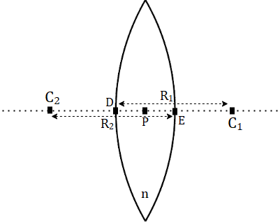
For the figure shown above (Figure 1), the lens maker’s formula is formulated as:
\(\frac{1}{f} = (n – 1)(\frac{1}{R_1} – \frac{1}{R_2})\)Where,
\(f\) is the focal length of the given lens
\(n\) is the refractive index of material used to make the lens
\(R_1\) and \(R_2\) are the radii of curvature of the 2 sides of the lens, as shown in Figure 1.
Figure 1 shows a (convex) lens with different radii of curvature, made out of a material with refractive index \(n\).
We make the assumption that this is a thin lens (as stated earlier), the points D, P and E (in figure 1) have a very small distance between them, which can be neglected.
Therefore, the radii of curvature of the left side of the lens is the distance C2E, approximately the same as the C2P – i.e., C2E ~ C2P = R2.
Similarly for the right side of the lens, C1D ~ C1P = R1.
Sign convention for Lens Maker’s Formula
Sign convention is very important for setting up the geometric relations that are used to derive the lens maker’s formula, and also for substituting the values in the final equation to obtain the focal length of the lens.
Let us now take a look at using sign convention appropriately.
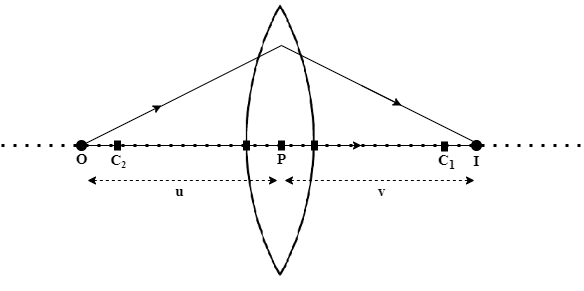
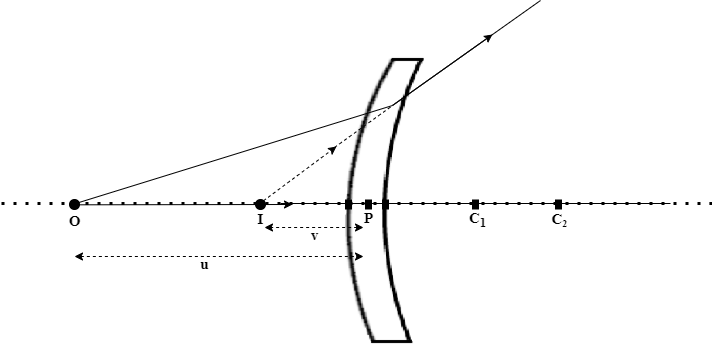
Consider the lens setup as shown in Figure 2. O is the point at which the object is placed on the principal axis of the lens. The above figure shows the image formation at I.
Let the distance between the center of the lens P and the object O be u units, and the distance PI is v units.
The sign convention states that,
1. The lengths measured starting from point P to the right side, should be given a positive sign, whereas 2. The lengths measured from point P to the left should be assigned a negative sign.
Therefore, for different lens setups shown below,

The sign convention will be as follows:
| Figure | u | v | f | R1 | R2 |
| 2 | – | + | + | + | – |
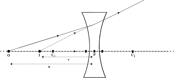
| 3 | – | – | – | – | + |
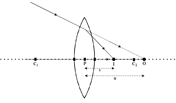
| 4 | + | + | + | + | – |
| 5 | – | – | – | – | – |
Note that in the above table ‘f’ is the focal length of the lens; these signs can be verified later using the lens maker’s formula that we shall derive.
Lens Maker’s Formula Derivation
Let us now take a look at the lens maker’s formula derivation.
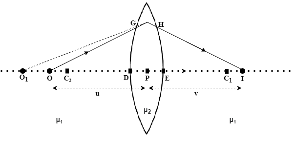
Consider the lens setup shown in Figure 6, similar to Figure 1. Here we have an object on the principal axis of the lens, marked O.
The final image of the object is formed at the point I. The lens is surrounded by a medium of refractive index μ1 (in this case, air). The lens itself is made out of a material of refractive index μ2.
In order to find out where the image I of the object O is formed, let us trace two light rays originating from O, OG and OP.
The ray OP is along the principal axis of the lens (perpendicular to the spherical surface) and hence passes through undeviated.
The ray OG is refracted at the boundary of the lens-air system and is deviated from its original path. While tracing this refracted ray backward to meet the principal axis of the lens will give us point O1 (say at a distance v1 from point P). Which is where the object would appear if someone were to observe it from inside the lens.
This point is now taken to be the new object position, and a light ray O1H originating from this point is drawn until point H.
At this point, we can also consider the entire left portion of the system to be a medium with refractive index μ2 since we have adjusted the position of the object as if one were observing from inside the lens.
Ray O1H now passes through the lens and once again into medium outside (air in this case) with refractive index μ1.
Since the refractive index of the material of the lens is higher than air (μ1 ~ 1), the deviation observed will be away from the normal drawn at the point of refraction. Therefore the refracted ray HI will be observed at shown.
Finally, the rays originating from point O (OI passing through the principal axis, and OG + HI) intersect at the point I on the other side of the lens, where the image is formed.
Now that we understand how an image is formed through a lens, let us try to arrive at the lens maker’s formula using the equation for refraction at a spherical surface, given by:
\(\large{\frac{\mu_2}{v} – \frac{\mu_1}{u} = \frac{\mu_2 – \mu_1}{R}} … (1)\)
Let us use this equation for the initial refraction of ray OG, taking the origin at point P (since the lens is thin, we can take the origin at point P instead of points D and E individually for each refraction).
In this case the object is at O, the image is at O1, and the centre of curvature for this refraction is at C2. Therefore we have:
\(\large{\frac{\mu_2}{v_1} – \frac{\mu_1}{u} = \frac{\mu_2 – \mu_1}{R_1}} … (2)\)
For the second refraction at the other boundary of the lens, the object is now taken to be at O1 (as explained earlier), which is at a distance v1 from point P.
The image is formed at I which is on the other side of the lens at a distance v, and the center of curvature for this refraction is at C1.
Therefore the equation for the second refraction is:
\(\large{\frac{\mu_1}{v} – \frac{\mu_2}{1} = \frac{\mu_1 – \mu_2}{R_2}} … (3)\)
Adding equations 2 and 3, we get:
\(\large{\mu_1(\frac{1}{v} – \frac{1}{u}) = (\mu_2 – \mu_1)(\frac{1}{R_1} – \frac{1}{R_2})}\)
\(\large{\frac{1}{v} – \frac{1}{u} = (\frac{\mu_2}{\mu_1} – 1)(\frac{1}{R_1} – \frac{1}{R_2})} … (4)\)
Since we want to find a formula for the focal length of the lens, let us assume that the object is now moved to infinity (i.e. u = \(\infty\)) which we know results in the image formation at v = f, the focal point.
Therefore:
\(\large{\frac{1}{f} = (\mu_2 – \mu_1)(\frac{1}{R_1} – \frac{1}{R_2})} … (5)\)
When a lens of refractive index μ is placed in air, then \(\mu_2 = \mu\) and \(\mu_1 = 1\). Equation 5 now becomes,
\(\large{\frac{1}{f} = (\mu – 1)(\frac{1}{R_1} – \frac{1}{R_2})} … (6)\)
Equation 6 is known as lens maker’s formula. Equation 7 is used in special case where the lens is placed in a medium other than air.
Note: Here we have assumed that the lens used is a thin lens. However, if the lens is not thin, the equation for this case is:
Thick Lens
\(\large{\frac{1}{f} = (\mu – 1)(\frac{1}{R_1} – \frac{1}{R_2} – {\frac{(\mu -1)d}{{\mu}R_{1}R_{2}}})} … (7)\)
Here, d is the thickness of the lens. This equation is more suited to real life use since thin lenses are only an ideal case.
We shall not dive into the derivation of Equation 7 as it involves concepts of Gaussian optics.
Solved Example
Question 1. A convex lens made out of glass (refractive index 1.5) has radii of curvature 10cm and 20cm. Find the focal length of the lens using the lens makers formula.
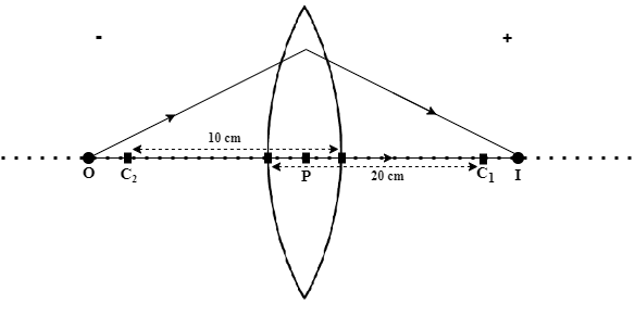
Solution. Using the sign convention that was stated earlier, we have:
\(R_2 = -10\)
\(R_1 = 20\)
\(\mu = 1.5\)
Substituting these values in the lens maker formula:
\(\large{\frac{1}{f} = (1.5 – 1)(\frac{1}{20} – \frac{1}{-10})}\)
\(\large{\frac{1}{f} = 0.5 * \frac{3}{20}}\)
=>\(\large{\frac{1}{f} = \frac{3}{40}}\)
Thus, \(\large{f = \frac{40}{3} cm}\)
Therefore, the focal length of the given lens is approximately 13.33 cms.
Note that, since the focal length is a positive value, we have to use the same sign convention as above to determine which side of the lens this lies. Since the right side of the lens indicates positive values, this implies that the focal point of this lens lies on the right side i.e. the same side as C1 in Figure 7 shown above.
Question 2. Given that the focal length of a bi-convex (convex on both sides) lens made with glass (refractive index 1.5) having equal radii of curvature is 20 cm, find the radii of curvature of the lens.
Solution: We have the following information given-
\(R_2 = R_1\)
Let \(R_1 = R\).Then \(R_2 = -R\)
\(\mu = 1.5\)
\(f = 20 cm\)
Since the lens is surrounded by air (uniform medium) and has the same radii of curvature on both sides, the system is symmetrical.
Substituting the above data in the lens maker’s formula:
\(\frac{1}{20} = (1.5 – 1)(\frac{1}{R} – \frac{1}{-R})\)
\(\frac{1}{20} = 0.5 * \frac{2}{R}\)
=>\(\frac{1}{20} = \frac{1}{R}\)
Therefore,
\(\large{R = 20 cm}\)
FAQ
For a thin lens, the lens maker’s formula is given as
\(\frac{1}{f} = (n – 1)(\frac{1}{R_1} – \frac{1}{R_2})\)
Where,
μ is the refractive index of the lens
f is the focal length of the lens
R1 and R2 are the radii of curvature of the lens.
The lens maker’s formula is used to determine the focal length of a lens given its radii of curvature (and also its thickness “d” in some cases). Since it gives the relation between the focal length, refractive index and the 2 radii of curvature of a lens, we can find out any of these quantities using the lens makers formula given that the other quantities are provided.
A Video On Lens Maker Formula
Related Topics