The Shockley diode is the first of the thyristor family of devices, named after its inventor William Bradford Shockley.
Index
The Diode
The four-layer semiconductor diode, the Shockley diode was one of the first semiconductor devices invented. It was named after the scientist William Shcokley. It’s a PNPN diode, with P-type and N-type material alternating layers. It’s the same as a thyristor with a broken gate.
This is not to be confused with a Schottky diode, which is a two-layer metal-semiconductor device with a fast switching speed. A four-layer package of P-N-P-N semiconductor material is a primitive example of the Shockley diode.
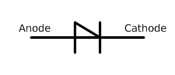
Shockley Diode Symbol
The symbol for Shockley diode is given as
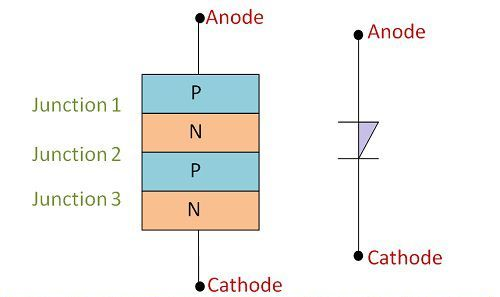
Construction of Shockley Diode
Shockley diode is made up of four layers of P-type, N-type, P-type, and one more N-type semiconductors squished together. The combination of four layers results in the formation of three junctions.
V-I Characteristics of Shockley Diode
- J1, J2, and J3 are the three junctions that make up the Shockley diode.
- As a voltage is applied to the diode, the anode terminal becomes positive in comparison to the cathode, J1 and J3 junctions become forward biassed, and J2 becomes reverse biassed.
- The following diagram depicts the V-I properties of a Shockley diode.
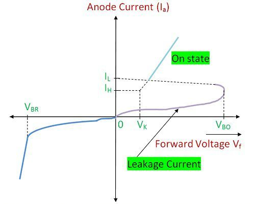
- The diode has two working modes: conducting and non-conducting. The conducting mode runs on the lower line with low current and a voltage less than the break over voltage.
- The system breaks down and switches on around the dotted line to the on-state as the voltage attempts to beat the break-over voltage.
- This line specifies a state that will only last for a short time.
- When it switches on between the two stable operating states, the system will have voltage and current values on the dotted line.
- The system operates on the greater line while it is on or conducting.
- The voltage through the device is slightly higher than knee voltage, VK, as long as the current across it is greater than the holding current IH.
- When the current falls below the holding current stage IH, the device returns to the off-state, following the dotted line.
Shockley Diode Equation
The Shockley diode equation, also known as the diode law, is the I–V (current-voltage) characteristic of an idealised diode in either forward or reverse bias (applied voltage). It is named after Bell Telephone Laboratories co-inventor William Shockley:
\(\large{I = I_s \left( e^{\frac{V_D}{nV_T}} – 1\right)}\)Where,
\(I\) = diode current,
\(I_S\) = reverse bias saturation current
\(V_D\) = voltage across the diode,
\(V_T\) = thermal voltage kT/q
\(n\) = ideality factor or emission coefficient
When n, the ideality factor, is equal to 1, the equation is known as the Shockley ideal diode equation. Depending on the fabrication process and semiconductor substrate, the ideality factor n usually ranges from 1 to 2 (though it can be higher in some cases), and is set to 1 in the case of an “ideal” diode.
The “levelling off” of the I–V curve at high forward bias due to internal resistance is not defined by the Shockley diode equation. This can be compensated by only adding a series resistance.
The exponential is very high for even very small forward bias voltages, since the thermal voltage is very small in comparison. The diode equation subtracted ‘1’ is then negligible, and the forward diode current can be approximated by
\(I = I_S e^{\frac{V_D}{nV_T}}\)
Limitations
Since four layers of semiconductor material are used, the construction is complicated.
Applications of Shockley Diode
Trigger Switch for a SCR
It is used to switch on the SCR or to activate it. The RC network is connected to the DC supply in the circuit below, and the capacitor starts to charge. When the voltage across the capacitor equals the Shockley diode’s break over voltage, the capacitor begins to discharge. The diode then switches to ON and provides gate current to the SCR, which turns it on.
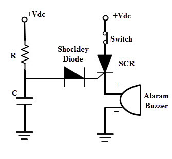
As a result, SCR is activated, and the alarm is activated. When the voltage source is shut off, the SCR stays in the conducting stage of the latch for a while. As a result, the Shockley diode is only used to turn it on.
Relaxation Oscillator
The capacitor is charged by a resistor, and when the voltage around the capacitor exceeds the break-over voltage, the diode is activated, resulting in a short circuit.
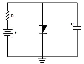
The capacitor then discharges through the Shockley diode, and the cycle begins again.
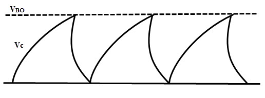
However, the capacitor does not fully discharge. The waveforms of the relaxation oscillator can be visualised using diagrams.
FAQs
A thyristor is a four-layer device with P-type and N-type semiconductors alternated on each layer (P-N-P-N). A thyristor has three terminals in its most simple form: anode (positive terminal), cathode (negative terminal), and gate (control terminal). The gate regulates current flow between the anode and cathode.
SCRs are mostly found in systems that need the control of high power, perhaps in combination with high voltage. They can be used in low- to high-voltage AC power control applications like lamp dimming, power regulators, and motor control because of their work.
Since there are no moving pieces in SCR, the process is quiet.
Extremely fast switching speed (say 109 operations per second).
Highly effective.
Read More on Diodes