A screw gauge is a tool used to measure very thin objects like sheets of metal or wires. It provides greater precision than Vernier’s Callipers. Sometimes it is also called a micrometre screw gauge.
Index
Screw Gauge Diagram
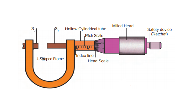
In the above diagram, we have the description of a Screw Gauge and its parts. Below we discuss the parts of this tool.
Parts of the Tool
The parts of this measuring tool are as follows:
- The U-shaped frame: the object to be measured is placed here, between S1 and S2.
- S1 (Screw). It is movable. It is adjusted by rotation of the thimble, till the object to be measured is firmly held between S1 and S2.
- S2 (Stud or Anvil). It is immovable. It and the screw hold the object in place.
- Hollow Cylindrical Tube: The Pitch Scale is engraved on this.
- Pitch Scale (Also called Main Scale): It is parallel to the main axis of the instrument.
- Head Scale (Also called Circular Scale): It is located on the circular part, in front of the milled head.
- Ratchet: It ensures that pressure is uniform between measuring surfaces. It is a safety device.
Screw Gauge Formula
The formula is given as follows:
\(\text{Total Length} = [(\text{Pitch Scale Reading}) + (\text{Circular Scale Reading}) \times (\text{Least Count})] mm\)Each of the terms are described below:
- Pitch Scale Reading (PSR): It is the reading on the pitch scale when the object is firmly held between stud and screw.
- Circular Scale Reading (CSR): It is the reading on the circular scale which is in-line with the pitch scale.
- Least Count (LC): It is given by-
- \(\text{Least Count of Screw Gauge} = \frac{(\text{Pitch of Screw Gauge})}{(\text{Number of Divisions on Circular Scale})}\)
- \(\text{Pitch of Screw Gauge} = \frac{(\text{Distance Travelled by Screw})}{(\text{Number of rotations})}\)
How to use Screw Gauge?
We can use this tool as follows:
- The object to be measured is place between S1 and S2.
- Zero error, if any, is recorded.
- The milled head is rotated to ensure that the screw rotates forward and the object is held firmly.
- We wait for the ratchet for to click thrice.
- The PSR and CSR are noted.
- The screw gauge formula is applied, and adjusted for zero error if needed.
Applications
This tool can be used to measure very thin objects like a wire or a thin sheet of metal. The least count is in the range of micrometre (10-6 m), so the instrument is also called a micrometer screw guage.
FAQs
It is an instrument used to measure very thin objects. It uses the principle of screw to work.
Pitch is the distance moved by the spindle per unit revolution. It is measured on the pitch scale, and is given by the formula:
\(\text{Pitch} = \frac{\text{Distance travelled by screw/Spindle}}{\text{No. of rotations}}\)
Formula of this tool is:
\(\text{Total length} = \text{(Pitch Scale Reading)} + \text{(Circular Scale Reading)} \times \text{(Least Count)}\)
The answer is usually in millimetres.
We can use this tool as follows:
1. The object to be measured is place between S1 and S2.
2. Zero error, if any, is recorded.
3. The milled head is rotated to ensure that the screw rotates forward and the object is held firmly.
4. We wait for the ratchet for to click thrice.
5. The PSR and CSR are noted.
6. The screw gauge formula is applied, and adjusted for zero error if needed.