A Sonometer is a device which uses the concept of standing waves to measure the mass per unit length or density of a wire. A sonometer is also called a Monochord.
Index
History
The first reference to a sonometer or monochord was found in the writings of the Sumerian empire. Some believe that Pythagoras reinvented the sonometer in the sixth century BCE. Robert Fludd invented the “Celestial Monochord” in 1618, which could be used as a musical tuner. The motivation for the development of the sonometer since then was to create a musical tuning device.

Sonometer Diagram
Sonometer Construction
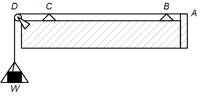
As shown in above figure, a monochord mainly consists of three parts:
1. The Wire, Weights and Pulley Apparatus
A wire is stretched along the soundbox, between the hinge A and the pulley D. The wire turns around the pulley to let a weight W hang on the end of the wire.
2. The Soundbox
The soundbox is a cuboidal box made of wood, upon which other parts of the sonometer are built. The function of the sonometer box is to amplify the sound of the tuning fork.
The sonometer box also has a graduated ruler along its length to measure distances on the box.
3. The Knife Edges
The knife edges are made to let the user change the length of the wire responsible for producing standing waves. So, changing the positions of the knife edges changes the wavelength of the standing waves. In the figure, knife edges are denoted by C and B triangles.
Sonometer Working: The Theory of Standing Waves
We can assume that there are two parts of the sonometer wire:
(a) The part of the wire between the knife edges and,
(b) The part of the wire other than the part between the knife edges.
Only part (a) is involved in a discussion of standing waves. Part (b) is the other supporting part, attached to the hinge A and weights W.
The waves produced on a stretched string are transverse. Standing waves can be considered as waves with wavelengths such that their antinodes coincide with the knife edges’ placement.
Mathematically this could be represented as:
\(l = \frac{n \lambda }{ 2 } \, ; \, n = 1, \, 2, \, 3, \, \dots\)Where, \(l\) is the length of the wire between the knife edges and \(\lambda\) is the wavelength of the transverse wave.
For \(n = 1\),
\(l = \frac{ \lambda }{ 2 } \Rightarrow \lambda = 2 l\) is called the fundamental mode of vibration.
We have,
\(v = \nu \lambda\)
\(v = \sqrt{ \frac{T}{m} }\)
Where,
\(v \rightarrow\) Velocity of the transverse wave
\(\nu \rightarrow\) Frequency of the transverse wave
\(T \rightarrow\) Tension in the wire
\(m \rightarrow\) Mass per unit length of the wire
We get for the fundamental mode,
\(\sqrt{ \frac{T}{m} } = \nu \times 2 l\)
\(\nu = \frac{1}{2l} \sqrt{ \frac{T}{m} }\)
Sonometer Experiment
Aim: To find the frequency of the AC mains using a sonometer.
Equipment Required: A sonometer apparatus, weights, step-down transformer, horseshoe magnet, connecting wires and AC mains power supply.
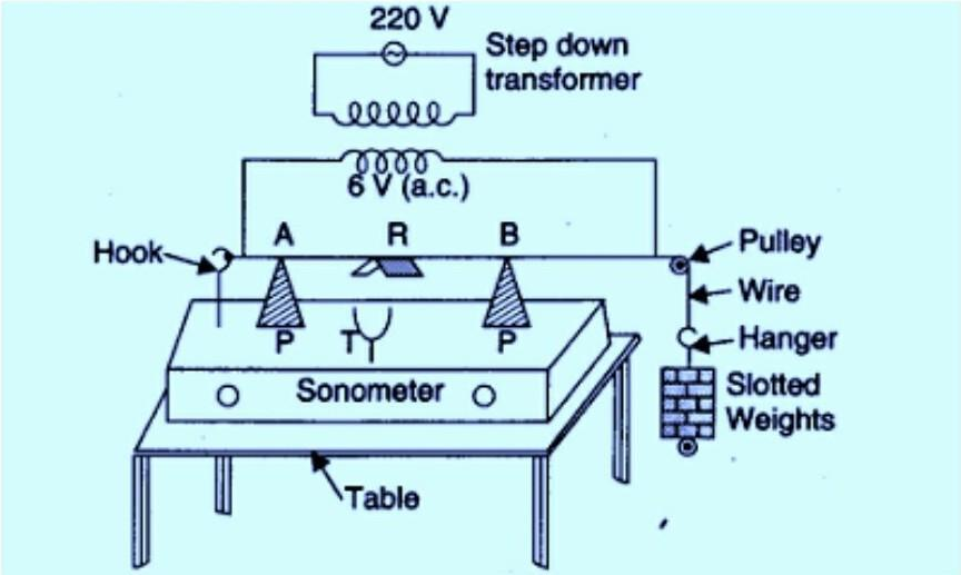
Circuit or Schematic Diagram:
Procedure:
- As shown in the circuit diagram, connect the primary coil terminals of the transformer to AC mains. Similarly, connect the secondary coil terminals to the end of the sonometer wire(one terminal at the hook/hinge; the other at the pulley).
- Place the horseshoe magnet symmetrically in the middle of the two knife edges. Place the magnet T so that the magnet’s magnetic field is perpendicular to the length of the wire.
- Hang a mass M at the end of the wire, and keeping it fixed, adjust the position of the knife edges so that the sound produced from the sonometer box is maximum. This could be confirmed when the paper rider R on the wire falls off. It represents maximum amplitude.
- Measure this length and repeat step 3 for different masses.
- Using a screw gauge, find the diameter and hence the wire’s cross-section area. Using the information about the density of the wire, find the mass per unit length m of the wire.
\(A = \frac{\pi D^2}{4}\)
\(m = \rho A\)
Where,
\(A \rightarrow\) Area of cross section
\(D \rightarrow\) Diameter
\(\rho \rightarrow\) Density of the wire
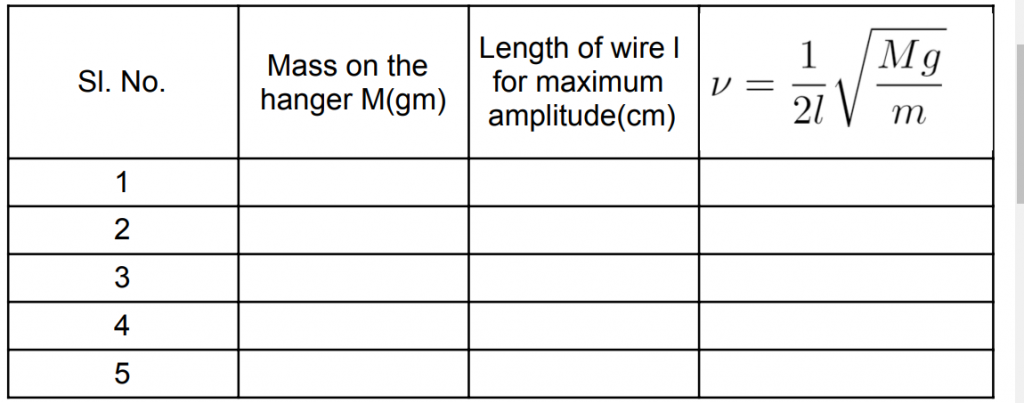
Observations Table:
Precautions:
- The mass M also contains the mass of the hangers. So make sure to take that into account.
- The wire should be uniform and free of any kinks or bends.
- When measuring the diameter of the wire with the help of a screw gauge, make corrections for the zero error. Take at least three readings and use the average of these readings.
- Make sure that the thickness of the sonometer wire is appropriate for the current passing through it. Use a rheostat if necessary.
FAQs
We require a magnet which provides a uniform magnetic perpendicular to the length of the wire. A horseshoe magnet is a perfect choice because the magnetic field is constant between the magnet’s arms.
A brass wire is used in the sonometer experiment. A brass wire is non-magnetic. Therefore, it is a natural choice.
Standing waves of Transverse nature are produced in the sonometer wire.
The sonometer box is built to have a broad resonance peak around a few tens of Hertz. So vibrations around a few tens of Hertz are near the resonance peak. The energy transfer is good in this range, and we hear a loud sound due to the resonating air column inside the sonometer box.